PCB Kits
PCB Kits
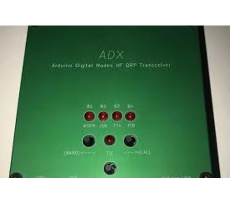
ADX (Barb Version) Bare PCB'SADX BARB Version Bare PCB Set (3 Boards) including Top Board, Motherboard, and Bottom Board. Modular stacked PCB system designed for RF and electronics projects. Supplied as bare PCBs only.
PCB Kits
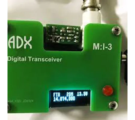
ADX - MI3 Bare PCBADX MI3 Bare PCB Set (3 Pack) including Top, Main, and Bottom boards. Precision-designed layered PCB system for RF and electronics builds. Supplied as bare PCBs only. Shown in assembled configuration for reference.
PCB Kits
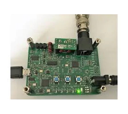
ADX -MI2 Bare PCBADX MI2 Bare PCB Set (3 Pack) including Top, Main, and Bottom boards. Precision-designed layered PCB system for RF and electronics builds. Supplied as bare PCBs only. Shown in assembled configuration for reference.
PCB Kits
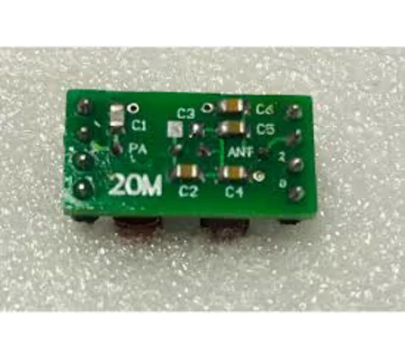
ADX MI3 Coded LPF Bare PCBADX MI3 Low Pass Filter Bare PCB for RF harmonic suppression and band filtering. Uses 0805 100V XR7 capacitors and 26AWG enamelled wire inductors. MI3 4-code band identification system. Supplied as bare PCB with instructions and winding sheet.
PCB Kits
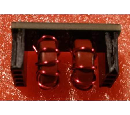
ADX MINI - MI2 LPF Bare PCBADX MI2 Low Pass Filter Bare PCB for RF harmonic suppression and band filtering. Uses 0805 100V XR7 capacitors and 26AWG enamelled wire inductors. MI2. Supplied as bare PCB with instructions and winding sheet.
ADX-FILTERS
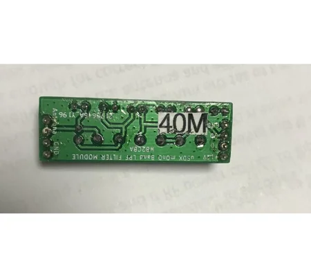
ADX QRP Serial Resonance Band Filter Bare PCBThis is the ADX Serial resonance Band filter module. The filter components are installed so as the ADX QRP can operate on a particular Band. Why did you make it? I am making available these filters since one may want to buy extra filters for the H.F Bands. What makes it special? Choose any filter you may need !. Supplied Ready built and tested.
PCB Kits
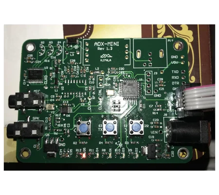
ADX-MINI Bare PCBADX MINI Bare PCB Set (3 Pack) including Top, Main, and Bottom boards. Precision-designed layered PCB system for RF and electronics builds. Supplied as bare PCBs only. Shown in assembled configuration for reference.
PCB Kits
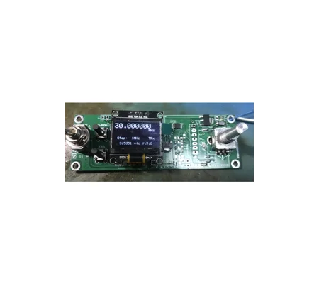
AVR ATMEGA + SI5351-VFO Bare PCBAVR ATMEGA328 + Si5351 VFO Controller Board with 3 independent clock outputs (TX, RX LO, IF/BFO). Supports 1 125 MHz output, RIT function, and calibration system. Ideal for HF/VHF radio designs. Supplied as bare PCB with instructions.
PCB Kits
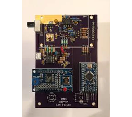
Arduino Antenna AnalyzerArduino Antenna Analyzer - Scans H.F Bands 1Mhz - 30Mhz
PCB Kits
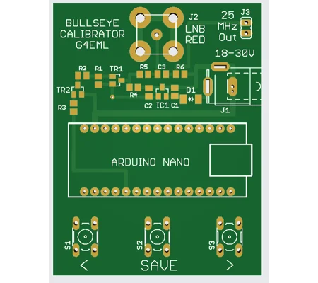
Bullseye LNB Calibrator SMD VersionThe Bullseye LNB Calibrator by G4EML is a compact Arduino based tool designed to precisely realign the Local Oscillator frequency of the Othernet Bullseye Ku Band LNB. Ideal for QO 100 and high accuracy satellite reception, it provides fast, reliable LO adjustment through simple push button control or USB terminal commands. Includes full open source firmware, schematics, and optional 3D printable POTY feed adaptors.
PCB Kits
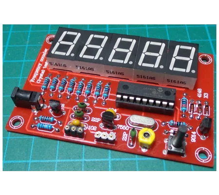
Classic Frequency Counter 1Hz-50MhzAcknowledgement: Credits to Wolfgang Buescher, DL4YHF, for designing this project (based on a work by James Hutchby, MadLab, 1996). What is it? This frequency counter kit measures frequencies from 1 Hz to 50 MHz and can also test quartz crystals. An onboard button accesses a menu to zero the scale or add/deduct an offset ideal for use with a shortwave receiver. The PCB is clearly labelled, making assembly very straightforward even for beginners. Why you'll love it: This is a low-component-count, high-value project. It's perfect for the ham shack, electronics lab, or as a teaching tool for learning about frequency measurement and microcontroller-based displays. Features: Frequency range: 1 Hz to 50 MHz Five-digit resolution (displays e.g., x.xxxx kHz, x.xxxx MHz, or xx.xxx MHz) Automatic range switching with variable gate times Programmable frequency offset (addition or subtraction) Optional input signal preamplifier Very low component count: PIC 16F628, five 7-segment LED displays, ...
PCB Kits
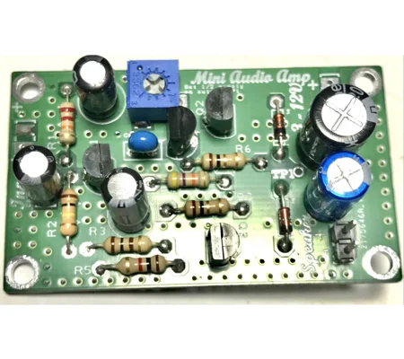
Discrete Audio AmplifierWhat is it? Mini Discrete Audio Amplifier Kit The mini discrete amplifier is an easy-to-assemble kit, perfect for beginners. It runs on a DC supply from 3V (with lower output) up to 18V and offers a voltage gain of 40dB (65dB power gain into 8Ω), matching the LM386 s performance but with less noise and hiss. At +12V, it delivers up to 0.5W into an 8-ohm load. Note: This is a high-gain circuit keep input wires short and well-routed. A 1mV (Hi-Z) input yields 50mV output at 8Ω, and distortion begins around 1V RMS output. Why did you make it? I wanted a simple audio Amplifier for one of the ongoing radio projects and did not want to use an audio chip and so i built this simple circuit. It works Just fine and Noise is very low and audio output is very clear and crisp. What makes it special? The amplifier was designed on a 2 sided screened board to keep the amplifier stable and away from oscillations and from any RF noise. It is very easy to build and use , consumes very little current a...